


July 1, 2026
Specifying a low-intensity radiant tube heater for a commercial application requires one foundational decision: forced draft systems or vacuum pull systems. The two configurations handle exhaust movement differently. For that reason, the choice carries consequences for safety, installation complexity, indoor air quality, and long-term reliability.
Why the Exhaust Mechanism Defines the System
Low-intensity radiant tube heaters move combustion gases from the burner through the heat exchanger tube and out of the building. By contrast, forced draft systems and vacuum pull systems accomplish that exhaust movement in opposite ways.
A forced draft system uses a blower at the burner inlet to push combustion gases through the tube. The blower creates positive pressure on the supply side. As a result, any leak in the tube assembly or the exhaust termination can release combustion gases into the occupied space. Positive pressure systems require well-maintained seals throughout the entire exhaust path.
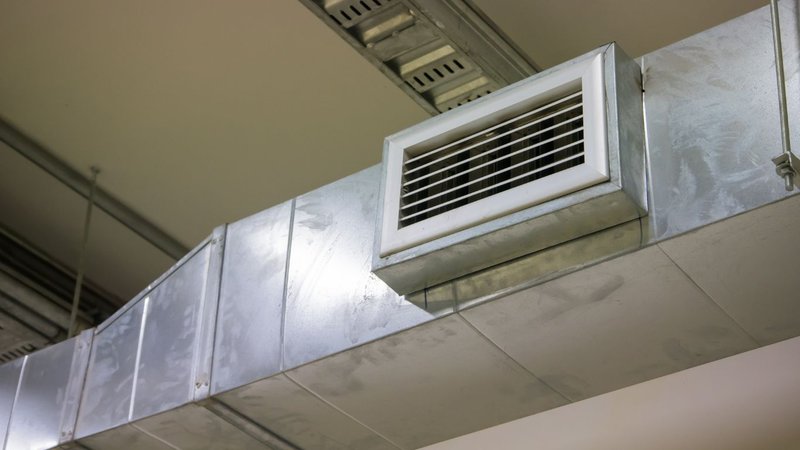
A vacuum pull system places the exhaust fan at the end of the tube rather than the beginning. The fan draws combustion gases through by creating negative pressure. Instead of pushing gases out, the system pulls them through. Any small leak in a vacuum system draws ambient air in rather than allowing combustion gases to escape. That characteristic makes vacuum-vented configurations inherently safer for occupied spaces. The Department of Energy addresses this distinction directly in its guidance on combustion safety for gas appliances using indoor air.
Forced Draft Systems in Commercial Applications
Forced draft systems are widely used where installation simplicity is a priority. The blower at the burner inlet is straightforward to size and service. These systems also suit applications with short exhaust paths and minimal fittings.
However, as exhaust path length increases, forced draft systems must work harder to maintain adequate flow. That load increases on the blower motor over time. When the building limits combustion air availability, indoor air quality can also be affected. The Omega II Pre-Engineered Package (PEP) from Combustion Research Corporation (CRC) uses a power-vented configuration. It suits commercial spaces where vacuum exhaust routing is impractical or where the exhaust run is manageable in length.
Vacuum Pull Systems in Commercial Applications
Similarly, vacuum pull systems operate under negative pressure throughout the tube assembly. The exhaust fan draws combustion gases through the heat exchanger tube from the burner end to the termination point. Because the system runs under vacuum, combustion gases cannot escape into the building interior. Furthermore, this condition holds even if minor imperfections exist in the tube seals.
CRC builds its Reflect-O-Ray Engineered Design System (EDS) around vacuum-vented operation. The system also draws combustion air from outside the building rather than from the occupied space. Together, those two characteristics isolate the combustion process entirely from the interior air. No combustion air comes from the space, and no exhaust gases can escape into it.
Vacuum systems also excel with longer exhaust runs. The fan at the end of the run creates a consistent draw along the entire tube length. CRC's patented spiral tubing design accelerates heat recovery within the tube. As a result, the system reaches optimum radiant output faster and maintains it more consistently across longer configurations.
Roof Penetrations and Installation Complexity
One practical advantage of vacuum-vented systems in commercial applications is the reduction in roof penetrations. Forced draft systems that exhaust through the roof typically require a penetration per heater or per zone. In a large facility, those penetrations accumulate quickly. Each one represents a water infiltration point and a weatherproofing obligation.
In addition, CRC's vacuum-vented systems can route multiple heaters to a common exhaust point in many configurations, reducing the total number of roof penetrations. That simplification also reduces installation labor and ongoing maintenance. NFPA 211, the standard governing venting systems for gas appliances, provides the framework for evaluating these exhaust routing configurations and the clearances each requires.
Static Pressure and System Performance
Both system types must manage static pressure within the exhaust path. Forced draft systems push against the resistance of the exhaust run. By contrast, vacuum systems pull against it. In either case, total static pressure affects combustion quality, burner performance, and heat output.
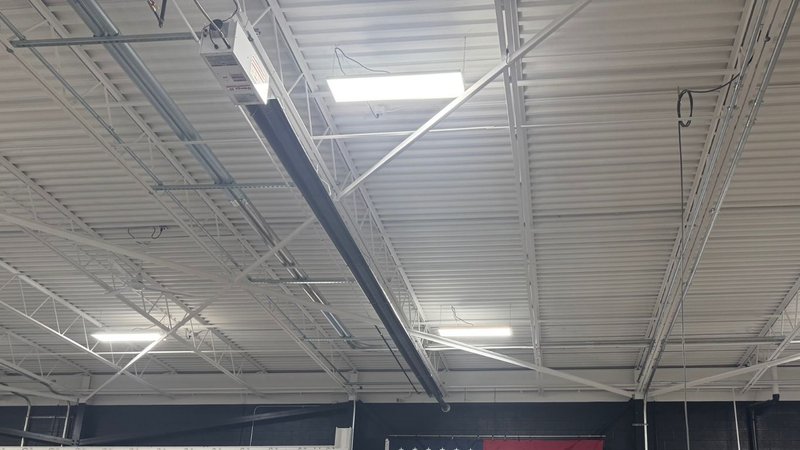
CRC engineers its systems around an optimum British Thermal Unit (BTU) input to tube length ratio. That ratio keeps exhaust temperatures below the threshold where dilution air becomes necessary. The article on infrared heat physics also covers why that ratio matters to overall system efficiency. For that reason, it is a useful reference for engineers evaluating either system type.
Maintenance and Long-Term Reliability in Forced Draft Systems
Both configurations require attention to the exhaust path over time. In forced draft systems, positive pressure increases the consequences of seal degradation. By contrast, in vacuum systems, the exhaust fan requires periodic inspection.
CRC minimizes maintenance demands through its filter-free combustion air design. Competing systems with combustion air filters create a recurring maintenance obligation. When those filters go unserviced, performance drops and failure risk rises. CRC removes that requirement by design. Every unit ships after individual testing rather than spot-checking. Each unit also carries a ten-year radiant tube warranty. The radiant tube longevity article covers how that design philosophy supports long-term performance across both system types. In addition, it explains the engineering decisions behind the warranty commitments.
Ultimately, the choice between forced draft and vacuum pull configurations should reflect the installation constraints, indoor air quality requirements, and maintenance expectations of each project. CRC’s greenhouse heater article provides a concrete example of how those configuration choices translate into real-world performance. To discuss which system fits a specific commercial installation, reach out to us to learn more about how we can help.