

July 6, 2026
A propane system sized using natural gas flow tables will starve downstream burners. In a multi-burner vacuum radiant installation, that error does not surface until commissioning. By then, the last heaters on the manifold fail to reach rated output. As a result, a propane pipe sizing calculator is not optional for multi-burner layouts. It requires propane-specific inputs and an understanding of how vacuum radiant systems behave under combined load.
Why Propane Pipe Sizing Differs from Natural Gas
Propane and natural gas have different specific gravities. Propane is heavier than air. It is also denser than natural gas, which means it flows differently through piping at the same pressure. Natural gas pipe sizing tables do not apply directly to propane systems. Using them without adjustment results in an undersized pipe that causes an unacceptable pressure drop at appliance inlets.
The practical consequence is a British Thermal Unit (BTU) shortfall across some or all of the burners. In a vacuum radiant installation where all burners run simultaneously, that shortfall produces uneven heat distribution. For that reason, propane-specific sizing inputs are essential for multi-burner layouts, not optional.
The Variables That Drive Accurate Pipe Sizing
Pipe sizing for a propane-fed radiant system depends on four primary variables. The first is the total connected load in BTU per hour, which determines the minimum required flow capacity at every point. The second is the allowable pressure drop between the regulator and each appliance inlet. The third is the run length for each segment, including equivalent lengths for fittings and valves. The fourth is the inlet pressure that the regulator delivers.
In a multi-burner installation with simultaneous firing, the design load must account for all burners at full input. As a result, under-designing for partial load produces a pipe that appears adequate on paper but fails under real operating conditions.
Pressure drop is also the variable that’s prone to miscalculation. Every foot of pipe, every elbow, and every tee contributes to the total drop. In addition, equivalent lengths for fittings must be added to actual run lengths before consulting sizing tables. In short, omitting fittings produces a result that looks correct on paper but fails under real flow.
Manifold Layout and Branch Sizing in Multi-Burner Systems
A multi-burner radiant installation distributes gas from a central supply point through a manifold to individual heater drops. The manifold must be sized for the combined load of all branches it serves. Each branch must furthermore be sized independently based on its load and run length from the manifold tap.
CRC's vacuum radiant systems use negative pressure. The Reflect-O-Ray Engineered Design System (EDS) and Omega II Pre-Engineered Package (PEP) both rely on this approach. Both pull combustion gases through the heat exchanger and exhaust them. However, this does not change the gas supply pressure requirement at the burner inlet. Each burner still requires adequate inlet pressure under simultaneous full-load conditions.
Pressure regulators at the manifold can help maintain consistent inlet pressure across branches of different lengths. Still, a regulator cannot compensate for a pipe too small to carry the required flow. That system-level coordination covers the heating, ventilation, and air conditioning (HVAC) planning that prevents these gaps from reaching commissioning.
Propane Storage and Vaporization Rate
Propane supply systems for commercial heating include not just the pipe network but also the storage vessel and vaporization capacity. Liquid propane must vaporize before it enters the gas piping. The vaporization rate of a tank depends on ambient temperature, liquid level, and tank surface area. In cold weather, large multi-burner installations can exceed the vaporization capacity of an undersized tank. As a result, pressure drops at the regulator in ways that the correctly sized pipe cannot address.
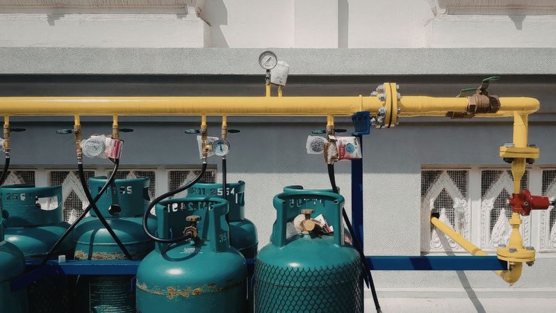
Tank sizing should account for peak demand at the coldest design conditions. This is also where CRC's fuel efficiency advantage is relevant. CRC infrared systems deliver substantial fuel savings compared to forced-air alternatives. Lower peak propane demand, in turn, reduces the tank capacity and vaporization infrastructure required.
Code Requirements for Propane Piping Installations
Propane piping installations are governed by the National Fire Protection Association (NFPA) Liquefied Petroleum Gas Code, NFPA 58. That code sets minimum requirements for container sizing, piping design, pressure regulation, and installation practices. For appliance-side piping and connections, the National Fuel Gas Code, NFPA 54, also applies.
Both codes require testing the system for leaks and pressure integrity before service. Contractors should furthermore confirm which edition each jurisdiction has adopted. Local amendments can affect allowable materials, pressure ratings, and installation practices.
Using a Propane Pipe Sizing Calculator
A propane pipe sizing calculator checks the pressure drop across each segment of the supply system. Most calculators require gas type, specific gravity, and inlet pressure as inputs. They also need the pipe material, nominal diameter, run length, and maximum allowable pressure drop. The output is the maximum flow capacity in BTU per hour or cubic feet per hour for each segment.
In practice, the calculation runs for each segment from the regulator to the farthest appliance inlet. The segment with the highest pressure drop determines whether the design meets the required inlet pressure at every heater. The American Society of Heating, Refrigerating and Air Conditioning Engineers publishes pipe sizing guidance in its Handbook Fundamentals. Engineers use those tables alongside NFPA 58 sizing tables for propane system design.
In addition, CRC's HVAC engineering representatives support contractors through the sizing process for Reflect-O-Ray and Omega II propane installations. In larger multi-burner projects, the spiral tubing design in CRC systems affects heat recovery performance. That performance interacts with fuel supply design in ways worth understanding before finalizing the pipe specification. Similarly, the radiant tube longevity article explains how CRC's design philosophy supports long-term performance in demanding propane applications.
Ultimately, a correctly sized supply network is where multi-burner propane radiant performance begins. Getting there requires propane-specific inputs, a manifold layout built for combined load, and storage sized for peak vaporization demand. Together, those three decisions determine whether the system delivers what it was specified to do. Contact us for more information.