Striping isn't just uncomfortable. It undermines the entire purpose of a radiant system. Workers in cold-striped zones reach for portable space heaters, facility managers crank up thermostats, and fuel bills climb — all because a spacing decision made on paper didn't translate to even heat at floor level.
Understanding why striping happens, and how to prevent it, starts before a single heater is mounted.
Key Takeaways
- Striping happens when radiant tube heaters are spaced too far apart, leaving cold gaps between their heat patterns at floor level
- Maximum heater-to-heater spacing should not exceed 2× the mounting height, per manufacturer guidance
- Higher ceilings, low-BTU heaters, and uniform layouts near high-heat-loss zones all worsen striping
- Prevention starts with a proper heat load calculation before equipment is specified, not after occupants start complaining
- Reflector quality and perimeter zone adjustments matter, but neither fixes fundamentally wrong spacing
What Is Striping — and What Causes It?
Striping describes a floor-level temperature pattern where occupants standing directly under a radiant tube feel warmer than those standing between two tubes. Move a few feet in either direction, and the temperature shifts. This "zebra stripe" effect signals both a comfort failure and an efficiency failure: heat is not reaching the floor uniformly.
Several root causes produce striping, and they tend to compound each other.
Tubes Spaced Too Far Apart
Each radiant tube projects heat downward in a spreading pattern. When the gap between adjacent tubes is too wide, those patterns don't overlap enough at floor level — cold bands fill the space between them.
Superior Radiant Products' layout guidelines state that the maximum distance between heaters should be no more than 2× the mounting height. A building with heaters mounted at 16 feet, for example, should have tubes no more than 32 feet apart center-to-center. Exceeding that ratio is the single most common cause of striping, and it's baked in at the specification stage — expensive to fix after installation.
Mounting Height Not Factored Into Spacing
The same tube spacing that delivers even heat in a 14-foot-ceiling shop will create pronounced striping in a 24-foot industrial bay. As mounting height increases, the heat pattern spreads over a longer vertical distance and arrives at floor level as a wider but cooler distribution.
A common mistake is retrofitting heaters originally sized for a lower-ceiling building into a taller structure without recalculating spacing. The numbers may look similar on a drawing, but the heat delivery at floor level is completely different.
Undersized BTU Output for the Spacing Used
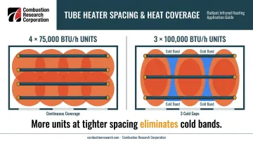
Spacing and BTU output are linked. A heater with insufficient output cannot project enough energy to create meaningful overlap between adjacent heat patterns — even if the spacing technically meets the 2× rule.
Infra-Red Radiant's layout guidance illustrates this directly: for a 300,000 BTU/h heat load, distributing that load across four 75,000 BTU/h units produces better floor-level coverage than using three 100,000 BTU/h units. More heaters with slightly lower individual output, placed at tighter intervals, eliminate the cold gaps that wider-spaced, higher-output units leave behind.
Ignoring Perimeter Heat-Loss Zones
Uniform tube spacing across an entire building assumes uniform heat loss — which is never true. Perimeter walls, large overhead doors, and loading dock openings lose far more heat than the building's interior. The same spacing that works in the center of a warehouse will feel cold near the edges.
Industry practice calls for positioning heater burner ends (the highest-output portion of the tube) near doors and cold walls. Infra-Red Radiant notes that proper perimeter placement can reduce perimeter heat loss by approximately 15%. Skip this step, and workers near overhead doors or loading docks will be working in temperatures 10–15°F colder than those in the building's center.
What Happens When Striping Goes Unaddressed
The effects compound quickly once striping takes hold.
Three problems tend to emerge when striping goes unaddressed:
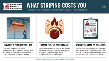
- Comfort and productivity losses. Workers in cold-striped zones adapt by clustering near warm spots or dragging in portable heaters. A Lawrence Berkeley National Laboratory study found office performance drops to 91.1% of maximum at 86°F (30°C) — and industrial workers in cold zones move more slowly and make more errors.
- Wasted fuel with no comfort gain. The typical response is raising the thermostat setpoint for the whole system. That overheats well-covered zones while barely touching cold ones, and energy consumption climbs with nothing to show for it.
- ASHRAE Standard 55 violations. ASHRAE limits acceptable vertical air temperature differences to 5.4°F (3°C) for seated occupants and 7.2°F (4°C) for standing occupants. Pronounced striping routinely exceeds both thresholds.
Warning Signs to Check For
- Occupants report warm spots in some areas and cold spots just a few feet away
- Floor-level temperature readings vary noticeably across the width of the space
- Thermostats cycle off in well-heated zones while perimeter areas stay cold
- Portable heaters appear near exterior walls, dock doors, or building corners
- Heating complaints cluster consistently in the same locations season after season
How to Prevent Striping: Getting Tube Spacing Right
Prevention is a design-stage discipline. Once heaters are mounted and gas lines are run, correcting spacing errors becomes a major expense. The decisions below need to happen before equipment is specified.
Start with a Proper Heat Load Calculation
Calculate the building's total heat loss in BTUs per hour, accounting for:
- Wall and ceiling insulation values
- Total ceiling height and volume
- Number, size, and frequency of operation for all overhead doors
- Climate zone and design outdoor temperature
- Infiltration from loading docks, drive-through bays, and building envelope gaps
This figure is the foundation for everything else. It determines total heater capacity needed, how that capacity should be distributed across the floor plan, and where spacing needs to tighten. Skipping this step and going straight to equipment selection is the design error most likely to produce striping.
Follow the Mounting-Height-to-Spacing Ratio
The verified industry guideline: maximum heater spacing = 2× the mounting height. At 20-foot mounting height, keep tubes no more than 40 feet apart center-to-center. At 14 feet, no more than 28 feet apart.
Two additional points that often get overlooked:
- The wall-offset distance (from the nearest tube to the wall) should be approximately half the spacing between tubes
- Perimeter rows should be positioned closer to exterior walls than standard center spacing would dictate
This ratio protects against heat pattern separation at floor level. Treating it as a maximum — not a target — gives you margin to work with.
Use High-Performance Reflectors to Direct Heat Uniformly
Reflector design directly affects how wide and how even the heat pattern is at floor level. A deep-dish, multifaceted aluminum reflector concentrates energy downward more effectively than a shallow "top-hat" style reflector. Deeper reflector profiles direct measurably more heat toward the floor and reduce sideways scatter — a direct factor in whether cold bands appear between tube runs.
Combustion Research Corporation's Reflect-O-Ray Engineered Design Systems are built around this principle. CRC's engineering support team works through the specification process for both new construction and retrofit projects — modeling heat distribution patterns, selecting reflector configurations, and laying out tube spacing based on actual building geometry and heat load.
That front-end modeling catches spacing problems on paper, before a single anchor bolt goes into the ceiling.
Tighten Spacing Near Doors, Docks, and Exterior Walls
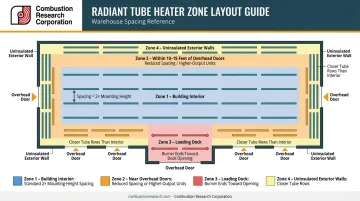
Variable spacing is standard practice for well-designed systems:
- Building interior: Standard spacing per the 2× mounting-height rule
- Within 10–15 feet of large overhead doors: Reduced spacing or higher-output units
- Loading dock areas: Position burner ends (highest output section) toward the dock
- Uninsulated exterior walls: Closer tube rows than interior sections
Solaronics notes that infrared tube heaters in loading dock applications recover heat within minutes after doors open — but only when the units are placed close enough to those high-loss zones to compensate for the cold air infiltration.
Establish variable spacing in the layout planning phase. Retrofitting it after installation is far more expensive than getting it right the first time.
Validate the Layout Before Mounting Is Finalized
Variable spacing and door-zone adjustments only hold up if the full layout is reviewed as a system. Before permanently mounting heaters or submitting a final layout drawing:
- Overlay the spacing plan on the heat load calculation output — confirm that BTU distribution across zones matches the heat loss distribution
- Check coverage at every section of the building, not just the center bay
- Verify perimeter rows are tighter than interior rows wherever doors or uninsulated walls exist
- Confirm the 2× mounting-height rule is met across all parallel tube runs
This review takes hours at the design stage. Correcting it after installation can take days and significant cost.
Other Factors That Contribute to Uneven Heat Distribution
Tube spacing drives most striping problems, but several other variables affect how evenly heat reaches occupants:
Tube Orientation
Tubes running perpendicular to the building's long axis create different overlap patterns than tubes running parallel. The choice affects coverage near walls and corners and should match the building's geometry, not default to whatever is easiest to run.
Building Obstructions
Mezzanines, large racking systems, overhead cranes, and vehicle lifts can block or deflect radiant energy, creating cold zones below the obstruction. Documenting every interior obstruction before finalizing a layout is standard practice in system design — skipping this step often shows up later as persistent cold spots.
Venting Configuration
Vacuum-vented systems like the Reflect-O-Ray allow multiple units to share a common exhaust manifold and a single roof penetration. That flexibility gives designers more room to optimize tube spacing without working around individual exhaust paths.
Power-vented systems like the Omega II handle back pressure well in longer exhaust runs but require careful attention to seal integrity at every joint. Either way, discuss venting requirements with your system designer early — vent routing directly constrains where tubes can physically go.
Tips for Long-Term Prevention and Consistent Comfort
Design gets you most of the way there — but these maintenance habits prevent striping from creeping back in over time:
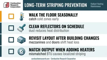
- Walk the floor with a thermometer during cold weather, taking readings at multiple points. Catching new cold zones early keeps them from turning into complaints.
- Clean reflector surfaces on a documented schedule. Dust, debris, or corrosion reduces heat distribution and widens cold bands even in a correctly spaced system.
- Revisit tube coverage after any major building changes. Adding a mezzanine, installing new overhead doors, or rearranging heavy racking shifts heat loss patterns — the original layout may no longer be adequate.
- Match BTU output to existing design parameters when adding heaters. Mismatched output in an otherwise well-designed system is one of the most common causes of localized striping in expanded areas.
Frequently Asked Questions
How far apart should radiant tube heaters be spaced?
For ceiling-mounted gas-fired infrared tube heaters, the maximum center-to-center spacing between heaters should not exceed 2× the mounting height per manufacturer guidelines. At 18-foot mounting height, that's a maximum of 36 feet between tubes. Tighter spacing is required near perimeter walls, overhead doors, and other high-heat-loss zones.
How many feet of PEX for radiant heat?
PEX tubing calculations apply to hydronic radiant floor systems, not ceiling-mounted infrared tube heaters. For floor systems, multiply the heated square footage by a spacing multiplier (1.0 for 12-inch spacing, 0.75 for 16-inch spacing).
What causes cold spots between radiant tube heaters?
Cold spots between tubes result from insufficient overlap between adjacent heat patterns at floor level. The most common cause is tubes spaced beyond the 2× mounting-height limit, or heaters with BTU output too low to project heat far enough to overlap with the adjacent tube's pattern.
Does ceiling height affect how far apart radiant tube heaters should be spaced?
Yes, directly. Higher ceilings require closer spacing (or higher BTU output) because heat spreads over a longer vertical distance and arrives at floor level with less intensity. Buildings with ceilings over 20 feet need spacing recalculated for that height, since copying spacing from a lower-ceiling application almost always creates striping.
Can better reflectors fix striping without changing tube spacing?
Improved reflectors help widen and direct the heat pattern from each tube, but they cannot compensate for tubes spaced well beyond the 2× mounting-height limit. Reflector upgrades work best as a complement to correct spacing — useful for fine-tuning distribution, not for covering a fundamental layout error.
Why do areas near loading dock doors feel colder even with radiant tube heaters installed?
Overhead doors and loading docks are concentrated heat-loss points. Standard uniform tube spacing is insufficient in these zones. Placing burner ends (highest output sections) toward those doors and tightening tube spacing within 10–15 feet of the opening is necessary to offset cold air infiltration and maintain comfort at floor level.