Many facility managers and contractors treat clearance as an afterthought, something to check once and forget. That's the mistake. Misreading the clearance zone, its boundary limits, or how mounting angle shifts it is a leading cause of failed installations, fire risk, and warranty disputes. Operating equipment was the leading heat-source category in U.S. warehouse fires between 2020 and 2024, accounting for 43% of incidents according to NFPA's warehouse structure fire data, a reminder that heating equipment clearance isn't a paperwork formality.
This article breaks down what clearances actually represent, how ranges shift with mounting angle, how to read a clearance chart correctly, and what happens when those numbers get ignored.
Key Takeaways
- Combustible clearance forms a mandatory 3D zone: top, sides, rear, and below
- Distances shift with mounting angle (0°-45°) and whether you measure from tube or reflector
- Approved side shields/BK extensions can legally reduce lateral clearance in tight retrofit spaces
- Manufacturer-documented minimums differ from recommended mounting height and should never be reduced
- Certified units tested to ANSI Z83.20/CSA 2.34 derive clearance data from lab testing, not estimates
What Radiant Tube Heater Clearances Represent
Clearance to combustibles is the minimum distance between the heater assembly and any combustible material, established through certified surface-temperature testing. That figure comes from lab testing under controlled conditions, tied to a specific model, not from a rule of thumb applied on-site.
That distinction matters because clearance is a hard design constraint validated during certification, not an adjustable variable an installer can change based on space limitations.
A unit that's CSA International Design Certified to ANSI/CGA Standards has already had its surface temperatures measured and its clearance figures locked in before it ever ships.
Clearance is fixed per model, not user-tunable. It's tied to three things:
- Tube length and diameter
- BTU rating
- Radiant surface temperature at full firing rate
Change any of those, and you're looking at a different unit with a different clearance chart.
This is why Combustion Research Corporation's Omega II and Reflect-O-Ray lines publish clearance figures that typically range from 12 inches to 60 inches, depending on the specific model and mounting orientation. There's no single number that applies across the board.
It's a Full 3D Zone, Not a Single Measurement
Clearance isn't one dimension. It's a volume that surrounds the heater on every side that matters:
- Top clearance protects ceiling structure and roof decking
- Side or front clearance protects walls, racking, and stored goods
- Behind clearance becomes relevant once a unit is angled
- Below clearance protects floor-level equipment, inventory, and vehicle traffic
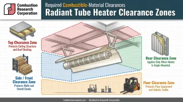
That zone has to stay clear permanently, not just on the day the inspector signs off. A pallet stack that creeps into the below-clearance zone six months later is just as much a violation as if it had been there on day one.
Factors That Influence Clearance Requirements in Real-World Installations
Brochure-listed mounting heights and actual required clearances aren't the same thing, and that gap causes real problems in the field. An economy-grade tube and a harsh-environment stainless steel tube of the same BTU rating can carry different clearance requirements because of how each is built and finished.
Construction differences that affect clearance:
- Powder-coated burner housings and aluminum reflectors versus stainless steel housings and reflectors used in corrosive environments (natatoriums, car washes, plating shops)
- Manufacturing tolerances in reflector angle, which change how radiant energy is directed
- Heat-exchanger tube gauge, which affects surface temperature under load
Duty cycle plays a role too. A heater running continuous industrial shifts builds up surface temperature differently than one cycling on and off in a lightly used space. Continuous operation is the more demanding condition, and it's the one clearance charts are tested against.
Then there's what happens after installation. Facilities change in ways the original clearance check never anticipated:
- Racking gets added near the heater zone
- Pallets of cardboard, tires, or parked vehicles drift into space that was clear at handoff
- Reflectors degrade over years of service, sometimes shifting the effective heat pattern
None of that shows up on the original inspection, which is exactly why clearance needs periodic re-verification, not a one-and-done check.
Clearance Ranges: Nominal Values, Tolerances & Safe Margins
There is no universal clearance figure. Ranges are governed by mounting angle, model design, and BTU rating, and pretending otherwise is how installations go sideways.
Nominal Clearance Values by Mounting Angle
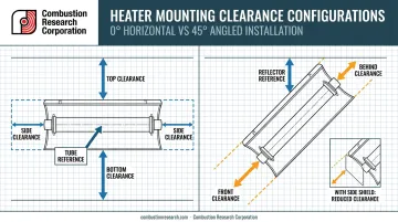
At horizontal (0°) mounting, clearance zones are typically symmetrical, with side clearances mirrored on both sides of the unit. One published tube heater clearance submittal shows how a 125,000 BTU unit's figures shift by angle:
| Mounting Angle | Side | Front | Behind | Top | Bottom |
|---|---|---|---|---|---|
| 0° (Horizontal) | 20 in | — | — | 6 in | 76 in |
| 45° | — | 58 in | 10 in | 8 in* | — |
*Measured from the reflector rather than the tube.
The symmetrical "side" clearance disappears entirely at 45°, replaced by directional front and behind values, because angling the unit pushes the hot zone forward.
This is why CRC directs specifiers to the submittal sheet for the exact model in question. Numbers here are illustrative of how angle reshapes a zone, not a substitute for your unit's documented chart. If you're mounting anywhere between 0° and 45°, use whichever published clearance is greater.
Allowable Tolerance and Reference Point Rules
Reference points change depending on angle, and that trips up more installers than any other clearance mistake. Some dimensions are measured from the tube surface itself. Others are measured from the reflector edge. Using the wrong one, even by a few inches, is a top cause of non-compliance found during inspection.
There's also no exception for short-term intrusions. Seasonal storage, a forklift parked overnight, holiday inventory stacked against a wall, none of it qualifies as acceptable. Industry guidance is direct on this point: required clearances to combustibles must be maintained at all times to ensure safety. No continuous-versus-momentary carve-out exists in that language.
Safe Operating Margins and Reducing Clearance with Side Shields
Manufacturers build margin into published clearance figures beyond the bare ignition threshold of common combustibles. That buffer accounts for reflected heat, airflow variation, and the reality that field conditions rarely match a controlled lab environment exactly.
In tight retrofits, side shields or BK extensions offer a legitimate way to reclaim space. These accessories block radiant energy in one direction, which allows a documented, manufacturer-approved reduction in lateral clearance on that side.
What doesn't work is shaving that margin yourself without an approved shield. The result is gradual heat buildup, accelerated material degradation, and a fire risk that grows quietly until something fails.
How Clearances Are Specified, Measured & Validated
Clearance is both a documented design specification and an ongoing field checkpoint. Treating it as a one-time install step is where most long-term problems start.
Specification and Documentation
Every certified unit ships with a clearance chart in its installation manual, cross-referenced to codes such as NFPA 54, the National Fuel Gas Code. That code directs listed infrared heaters to be installed according to the manufacturer's own clearance instructions rather than a single fixed industry number.
CRC's Omega II, Reflect-O-Ray, and Synergy lines are Design Certified to ANSI/CGA Standards and tested to ANSI Z83.20/CSA 2.34. Units built to that standard derive their clearance data from independent lab testing, not a manufacturer estimating a safe distance on paper.
Measurement and Field Verification
Field verification is straightforward with the right tools:
- Identify the correct reference point for your mounting angle, tube or reflector, per that model's chart
- Measure with a tape measure or laser distance meter from that reference point to the nearest combustible surface
- Compare against the published minimum, using the greater of any two applicable angle values
- Document the measurement for inspection and warranty records
That documented measurement reflects conditions on install day, not necessarily conditions six months later. Lab testing happens under controlled conditions. Your facility isn't a lab. Reflected heat off a nearby wall, stacked inventory changing airflow patterns, or a busy HVAC system can all shift effective surface temperatures compared to how the unit was originally tested.
That's why clearances should be re-measured whenever facility layout changes, such as new racking, new equipment, or reorganized storage, not only at initial installation. CRC's engineering support network exists specifically to help confirm clearance configuration before installation, not after an inspection failure.
Risks of Operating Outside the Recommended Clearance Range
Ignoring clearance limits starts small and gets expensive. Paint on a parked vehicle discolors. Plastic bins nearby soften or warp. Wood shelving dries out and cracks faster than it should. None of that looks dramatic at first.
Left unaddressed, cosmetic damage becomes something worse. Continuous heat exposure on combustible material inside the clearance zone doesn't just degrade it; it moves the material progressively closer to ignition over time.
The practical consequences compound quickly:
- Manufacturer warranty coverage, including CRC's 10-year limited warranty on burner cores and heat exchanger tubes, can be voided when clearance requirements in the installation instructions aren't followed
- Fire marshal and insurance inspections can fail outright
- Repeated re-inspection cycles add cost and delay to projects that should have been closed out already
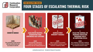
These consequences often trace back to one root cause: confusing two different documents. The most common misinterpretation in the field is treating a brochure's "recommended mounting height" as interchangeable with mandatory clearance-to-combustibles figures.
Mounting height governs performance and heat distribution. Clearance governs what's legally allowed to sit near the unit, full stop, regardless of mounting angle or model.
Final Thoughts
Clearance to combustibles is a governing safety parameter engineered into the heater itself, not something an installer adjusts on-site to fit a tight space. It's tested, certified, and documented for a reason.
Getting it right requires:
- Understanding the clearance ranges for your specific heater model
- Knowing which reference point applies at your mounting angle
- Re-checking the zone whenever your facility layout changes
Skipping these steps risks turning a compliant installation into a warranty dispute the moment an inspector shows up.
For new construction or retrofit projects, engineering support through the specification process, available through CRC's representative network, helps confirm the correct clearance configuration before equipment goes up rather than after an inspector flags it.
Frequently Asked Questions
What ceiling height is needed for radiant tube heaters?
Required ceiling height depends on the model's below-unit clearance to combustibles plus its mounting angle. Check the manufacturer's submittal sheet for exact minimums by BTU rating and tube length.
Where should radiant tube heaters be placed?
Position units so their full 3D clearance zone, top, side, front or behind, and below, stays permanently free of combustibles, storage, and vehicle paths, including future layout changes.
What is the minimum clearance to combustibles for a radiant tube heater?
Minimums vary by model, BTU rating, and mounting angle; there's no single figure that applies universally. Always confirm the exact distance against that specific unit's certified clearance chart before installation.
Do side shields really reduce required clearance distances?
Yes, when they're approved accessories documented by the manufacturer. Side shields or BK extensions block radiant energy in one direction, which can legally reduce lateral clearance in that documented configuration only.
Is recommended mounting height the same as clearance to combustibles?
No. Mounting height is a performance recommendation for even heat distribution, while clearance to combustibles is a mandatory safety minimum that can't be reduced regardless of mounting preferences.
Does mounting angle change the required clearance distances?
Yes. Angling a heater, typically 15° to 45°, shifts the required clearances and changes whether measurements start from the tube or the reflector. Check the manufacturer's chart for that specific angle.