Combustion Research Corporation has engineered low-intensity infrared heating systems for more than 50 years, and one lesson holds true across every project: venting isn't one-size-fits-all. Results depend on heater length, whether you're running a vacuum-vented or power-vented system, how the pipe is routed, and the limits set by both the manufacturer's IOM and applicable code.
This guide covers venting types, the step-by-step installation process, the parameters that affect performance, and the mistakes that generate the most service calls.
Key Takeaways
- Nearly all gas-fired radiant tube heaters require outdoor venting.
- Unvented use applies only to specific listed configurations with code-mandated makeup air.
- Vacuum-vented and power-vented systems carry different length, elbow, and common-venting rules.
- Vent length, pipe diameter, and termination clearances affect combustion quality and trigger safety lockouts.
- Manufacturer IOM manuals and ANSI Z83.20/CSA 2.34 standards govern every compliant venting decision.
Do Radiant Tube Heaters Need to Be Vented?
Most gas-fired low-intensity infrared tube heaters must exhaust combustion gases outdoors. The certification standard governing these products, ANSI Z83.20/CSA 2.34, covers heaters "designed for connection to a vent" and, separately, heaters "not designed for connection to a vent," spanning vent Categories I through IV.
In practice, the certified configuration and the manufacturer's instructions determine whether a unit vents outdoors, not the generic term "radiant tube heater."
Every heater CRC manufactures falls on the vented side of that line:
- Reflect-O-Ray systems operate as vacuum-fired, negative-pressure units requiring exhaust termination
- Omega II and Serengeti-IR are power-vented, unitary systems with their own dedicated flue path
None of CRC's product families are certified for unvented operation. That's a design characteristic, not an installation option.
The rare exception: unvented infrared heaters do exist, but they require a substantial air-handling commitment. The 2024 International Fuel Gas Code specifies that unvented infrared heaters need outdoor ventilation air supplied at not less than 4 cfm per 1,000 Btu/h of aggregate input, with exhaust openings positioned above the heater.
Most facilities find it simpler to vent the heater outdoors than to engineer around that requirement.
Why the caution matters:
- CO is colorless and odorless, produced by incomplete combustion of natural gas and other fuels
- Concentrations can build to dangerous levels within minutes, even in spaces that look adequately ventilated
- The exposure limit referenced above is easy to exceed once a vent restriction or leak develops
Improperly vented systems create a direct occupant-safety hazard. Professional, code-compliant installation through a qualified mechanical contractor, checked against both the heater's IOM and the adopted mechanical code, is non-negotiable.
Types of Venting Systems for Radiant Tube Heaters
Manufacturers offer different venting configurations to match building layout and heater run length. CRC's tube heaters come in both vacuum-vented and power-vented configurations, so the choice usually comes down to facility layout, unit count, and how much routing flexibility a project needs.
Vacuum-Vented (Negative Pressure) Systems
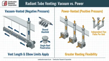
A single exhauster at the end of a heater run pulls combustion air through the entire tube run. This is common in continuous multi-heater installations, like CRC's Reflect-O-Ray EDS systems used across large warehouses and aircraft hangars.
The trade-off: vacuum systems carry stricter vent length and elbow limits than power-vented alternatives.
The payoff can be substantial. Multiple units can share a common exhaust manifold and a single roof penetration, cutting installation cost and preserving roofing integrity. In high-bay hangar applications, this common-venting approach can cut the number of required roof penetrations dramatically compared to venting each heater separately.
Power-Vented (Positive Pressure) Systems
An integral blower pushes combustion gases through the vent instead of pulling them. That gives installers more flexible routing and greater equivalent vent length per heater than a vacuum system typically allows.
The catch: each unit vents independently. CRC's Omega II and Serengeti-IR lines are built as unitary, single-side-vented systems, meaning every heater has its own combustion air intake, burner, and flue path.
That design simplifies zoning, since you can control each unit individually, but it requires a dedicated vent run per heater rather than a shared manifold.
B-Vent (Category I) vs. Category III Vent Explained
B-vent, also called Type B gas vent, is a double-wall Category I vent designed for natural-draft, non-condensing appliances operating at non-positive vent static pressure. It's not built for the operating conditions most radiant tube heaters produce.
Because radiant tube heaters typically run under positive vent pressure with higher flue gas temperatures, they require Category III vent pipe, usually stainless steel and rated for pressure-tight, gas-tight joints. DuraVent's own Type B installation instructions explicitly prohibit its use on Category II, III, or IV appliances.
Before buying materials, confirm the vent pipe category and diameter against the specific heater model's IOM. CRC's owner's manuals library lists model-specific venting requirements. Don't assume compatibility based on the vent type used on a previous project.
How to Vent a Radiant Tube Heater: Step-by-Step Process
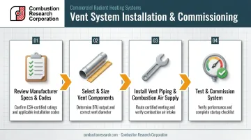
Step 1: Review Manufacturer Specs and Local Codes
Start with the paperwork, not the pipe:
- Check the heater's IOM for maximum vent length, elbow count, and pipe diameter matched to its BTU input
- Confirm the layout complies with ANSI Z83.20/CSA 2.34 and any applicable local mechanical or building codes
- Identify a compliant termination location with proper clearance from doors, windows, and air intakes before finalizing anything
Step 2: Select and Size Vent Components
Once the layout is confirmed on paper:
- Choose vent pipe material and diameter matching the heater's vent category and the manufacturer's approved parts list
- Calculate total equivalent vent length, adding each elbow's rated straight-pipe equivalent to the actual run and comparing that total against the maximum allowance
- Gather required hardware, including vent caps, wall or roof thimbles, firestop spacers, and support hangers
Step 3: Install Vent Piping and Combustion Air Supply
Assemble and secure the vent piping per the manufacturer's slope and support-interval instructions to prevent sagging over time. As a general benchmark, listed Category III systems commonly call for a slight upward slope away from the appliance, with supports every several feet. Always verify exact figures in the heater's IOM rather than assuming a universal number.
If the installation requires ducted combustion air intake, maintain the required separation from the exhaust termination. Seal every joint per the manufacturer's sealant or gasket specification. On positive-pressure systems especially, a loose joint can push flue gas into occupied space, creating a serious safety hazard.
Step 4: Test and Commission the System
Perform startup and verify flame pattern, draft, and vent operation against the commissioning checklist in the IOM. Check for spillage at the vent connector using a mirror or combustion analyzer before signing off. Document the final vent configuration and inspection results for code records and future maintenance reference.
Key Parameters That Affect Venting Performance
A correctly installed vent still underperforms if these variables aren't controlled.
Maximum Vent Length and Elbow Count
Why it matters: Exceeding the manufacturer-rated equivalent length increases back-pressure, which can cause incomplete combustion or trigger safety lockouts.
Impact on performance: Heater tube and reflector length often counts toward total vent length on the heater's own equivalent-length calculation, reducing the distance left for actual routing. Don't treat extra tube sections as free venting capacity.
Vent Pipe Diameter and Material
Why it matters: An undersized diameter restricts flue gas flow, while the wrong material can degrade under sustained high flue temperatures.
Impact on performance: Correctly sized, properly rated pipe maintains the design draft and avoids premature vent failure. Matching diameter to BTU input isn't an optional detail; it's a core design requirement.
Termination Location and Clearances
Why it matters: A termination placed too close to intakes, doors, or grade level risks recirculating flue gases back into the building.
Impact on performance: Per 2024 IFGC Table 503.8, nondirect-vent terminals require these minimum clearances:
- 4 feet below or to the side of an openable door or window (1 foot if above)
- 10 feet from a mechanical air-supply inlet
- 12 inches above grade or a deck surface
Meeting these numbers prevents nuisance shutdowns and protects occupants.
Common Mistakes and Troubleshooting Venting Issues
Even experienced installers make preventable venting errors that turn into service calls. The most common ones include:
- Treating extra heater tube or reflector sections as "free" venting capacity and unknowingly exceeding the maximum vent length
- Using an incorrect vent category, such as B-vent, on a heater that requires Category III pipe
- Failing to maintain proper clearance between the vent termination and the combustion air intake
Troubleshooting Common Venting Problems
| Problem | Likely Cause | What to Check |
|---|---|---|
| Heater trips on safety lockout shortly after startup | Vent length/elbow count exceeds the rated maximum, or a blocked/iced termination is restricting draft | Measure actual equivalent vent length against IOM limits; inspect termination for obstructions |
| Soot or discoloration near vent connections | Incomplete combustion from inadequate combustion air or incorrect gas pressure | Verify combustion air intake sizing; confirm manifold gas pressure matches heater specifications |
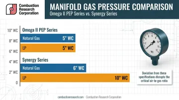
Manifold pressure is a critical variable, not an afterthought. CRC's Omega II PEP series is calibrated to 5 inches WC for both natural gas and LP, while Synergy models run at 6 inches WC (natural gas) or 10 inches WC (LP). Deviating from those figures disrupts the air-to-gas ratio the burner was calibrated for, creating a direct path to soot formation.
Frequently Asked Questions
Do radiant tube heaters need to be vented?
Yes — most gas-fired radiant tube heaters must vent combustion byproducts outdoors per manufacturer certification and mechanical code. Rare unvented exceptions exist but require substantial dedicated makeup air.
Are radiant tube heaters safe?
Yes, when properly vented, installed, and maintained per code and the manufacturer's IOM. They're a widely used, well-established heating solution across warehouses, hangars, and manufacturing plants.
What is the B-vent for tube heaters?
B-vent is a Category I vent designed for natural-draft, non-condensing appliances. Most radiant tube heaters operate under positive pressure and require Category III vent pipe instead.
Can multiple radiant tube heaters share a single vent?
Vacuum-vented systems allow multiple heaters to common-vent through one manifold and roof penetration. Careful sizing is required to avoid pressure imbalances across the run.
What happens if a radiant tube heater's vent is too long?
Exceeding the maximum equivalent vent length raises back-pressure in the system. That risk shows up as incomplete combustion, soot buildup, or a safety lockout shortly after startup.
How often should heater venting be inspected?
Plan on an inspection each heating season at minimum. Check for leakage, corrosion, blockage, and ice buildup at the termination per the manufacturer's guidance and your heater's IOM.